Triple Redundant
IREG© is a compact, modular designed system for excitation and voltage control of synchronous machines. It also uses alternating and direct current exciters for static systems.
IREG© provides a wide performance and flexibility for motor- and generator applications. Limitation and additional control functions can easily be designed and implemented by the operator, according to the specific plant capabilities.
IREG© is connected to a power stage called “IREG-power” in the basic version. The implemented CAN-Bus topology allows the operation of up to 3 IREG voltage regulators and 3 IREG-power modules simultaneously. Hot-Standby, redundancy and TMR (Triple Modular Redundancy) can be implemented easily, according to the needs of the mission-critical plant processes.
01. Diagnosis
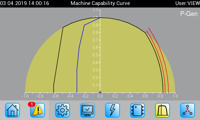
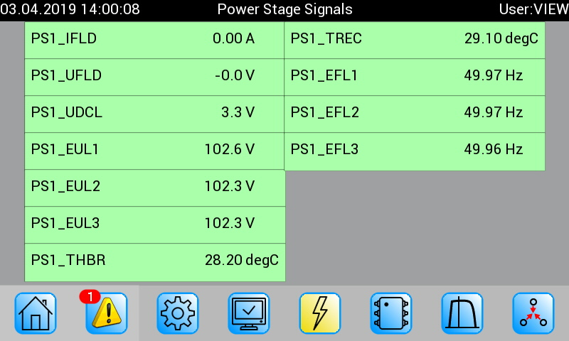
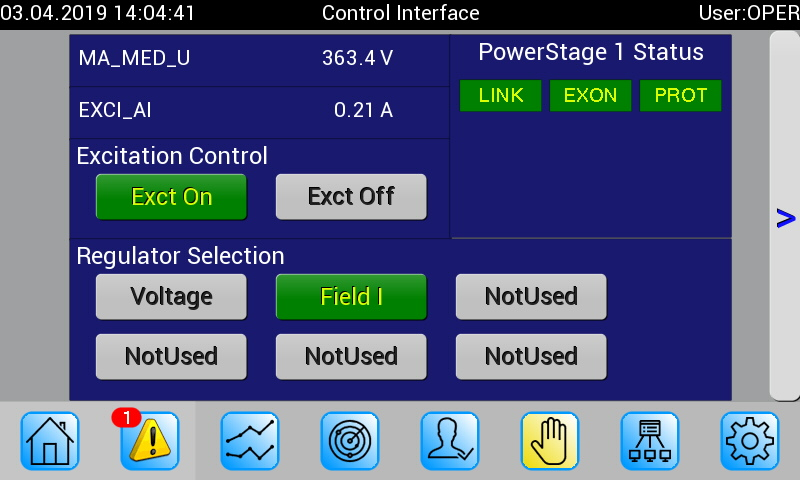
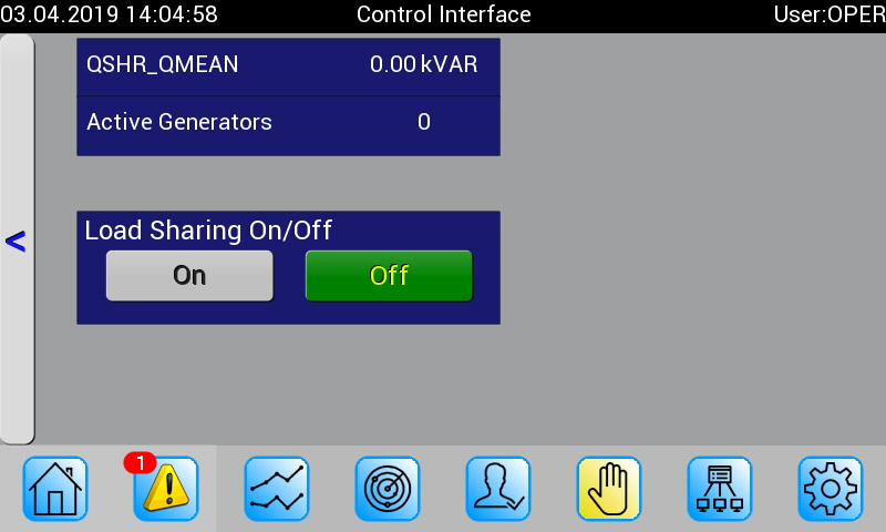
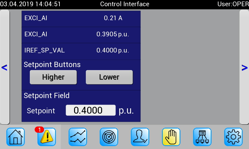
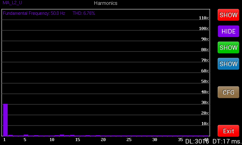
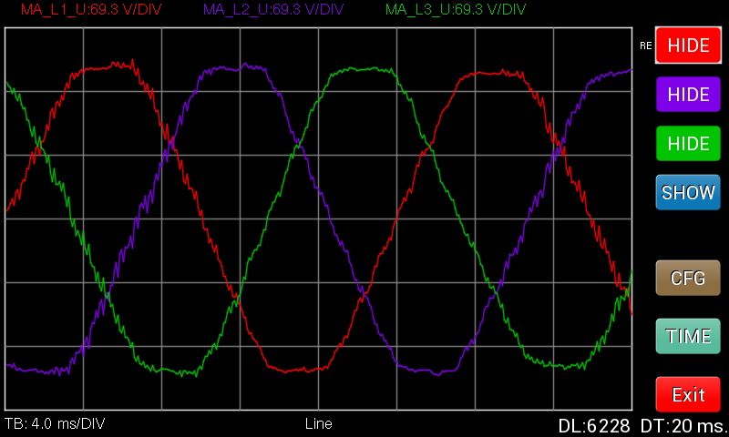
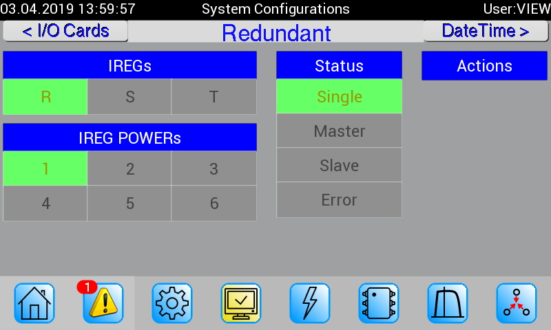
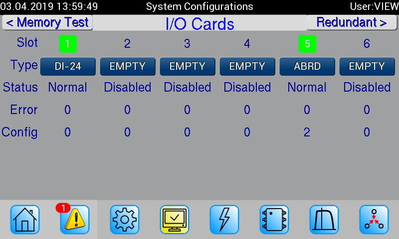
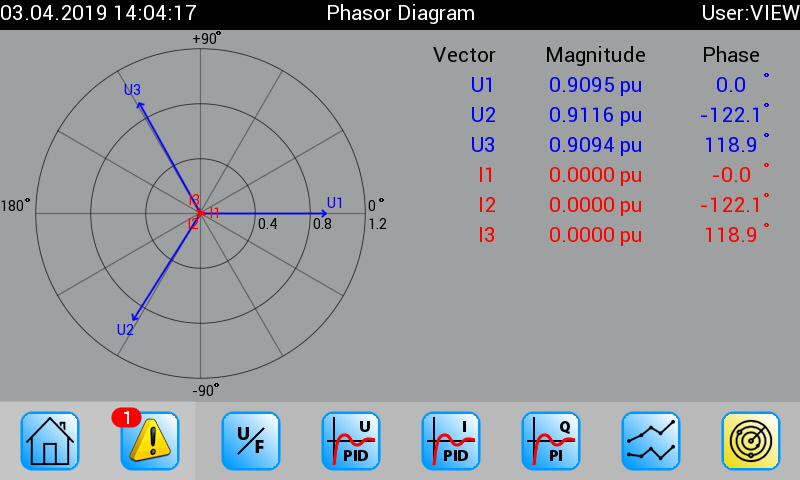
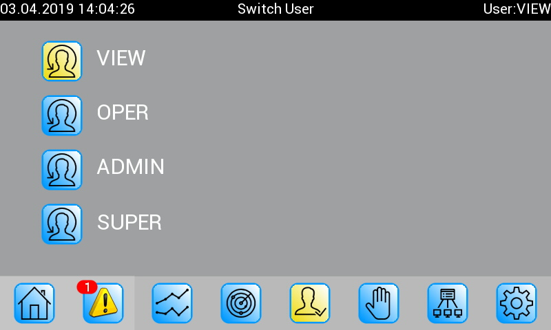
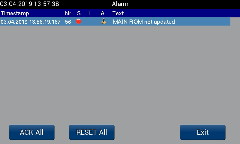
An innovative and full graphic colour touch screen provides access to the necessary control and monitoring functions, as well as the diagnostic and alarm lists.
02. USB Update
The Firmware updates or extensions of functionality can be loaded via the USB port located on the front panel or over the engineering software directly. An extensive, permanent self-monitoring guarantees a high degree of system stability.
03. Engineering
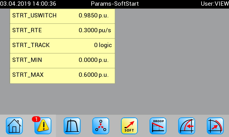
Thanks to the clearly structured functional groups and the innovative commissioning tools, it is easy to adapt or modify the parameters to the plant-specific conditions.
Comfortable operation
Touchscreen components
The integrated touchscreen panel allows you to easily achieve all the functions for visualizing and operating the IREG. The resolution is 800 x 480 pixels and is easy to read.
Functions
Limitations
External Setpoint Selection
Functions
Functions of the IREG voltage controller
Available functions can be activated or combined via the engineering tool. Thereby it is possible to parameterize a superimposed control (voltage regulator output = current regulator input), resulting in the ability to customize the corresponding IEEE models.
| Note | ||||
|---|---|---|---|---|
| Voltage Control | Regulating accuracy <=0.2% | |||
| Current Control | ||||
| Reactive Power Control | IEEE 421.5 Typ II PI | |||
| Reactive Power Control (q/u) | VDE-AR-N 4110 / 4120 | |||
| Reactive Power Control (q/p) | VDE-AR-N 4110 / 4120 | |||
| Power Factor Control | IEEE 421.5 Typ II PI | |||
| Diode Monitoring | On rotating diodes | |||
| Motor Soft Start | ||||
| Synchronizing | 3 phase, own CPU | |||
| Synchrocheck 1 | 3 phase, own CPU | |||
| LB response time measurement | 10-1000ms |
Limitations
Limitations
The individual limitations can be activated and parametrized via the Engineering Tool. The IREG complies to all requirements of TAR medium voltage (VDE-AR-N 4110) and TAR high voltage (VDE-AR-N 4120)
| Note | ||||
|---|---|---|---|---|
| Underexcitation | IEEE 421.5 Model II | |||
| U/F | ||||
| Overexcitation | ||||
| Stator Current | ||||
| Stator Voltage | ||||
| PSS | PSS2A/B PSS4B | |||
| Alpha min max | on AC Systems |
External Setpoint Selection
External Setpoint Selection
The set value can be made from multiple sources. The corresponding priority rule is determined via the engineering tool.
| Generator Voltage | ||||||
| Excitation Current | ||||||
| Reactive Power | ||||||
| Power Factor Control | ||||||
| Reactive Power Grid | ||||||
| Power Factor Grid |
Inputs and outputs of the IREG©
The inputs and outputs of the IREG© are grouped on the corresponding I/O cards. The signals of the I/O cards provide them to the processor. The signals of the I/O cards are made available to the processor in an isolated manner. The general input and output functionality is freely programmable. The transducer signals are hardware decoupled and led up in double to each DSP.
The DSP processor provides the actual current, voltage, power factor, active power, reactive power, phase angle, and other measurement values. On different measurement results, a secure system state is entered.
The synchronization feature is carried out directly by the DSP’s, where one processor executes the synchronization task and the other one the synchro-check function.
The connection to the field is implemented using industrial connectors.
| Specification | Sampling | Note | ||||
|---|---|---|---|---|---|---|
| Digital Inputs | 24-250VDC | 1kHz | Programmable | |||
| Digital Outputs | 250VDC, 8A constantly | Programmable | ||||
| Potential Transformer Inputs | 100-400VAC 16,7-400Hz | 16bit, 10kHz | ||||
| Current Transformer Inputs | 1A or 5A 16,7-400Hz | 16bit, 10kHz | ||||
| Analog Inputs | 0-20mA, 4-20mA | 16bit, 10kHz | Programmable | |||
| Analog Outputs | 0-20mA, 4-20mA | 16bit, 10kHz | Programmable | |||
| CAN-A, CAN-B, CAN-C | CAN Bus | |||||
| Exc. Current Measurement | Module dependent | |||||
| Excitation Energy | Module dependent | |||||
| Excitation Power Output | Module dependent | |||||
| Sync. Breaker On | 250VDC, 8A constantly | 1x Sync, 1x Check | ||||
| Sync. Digital Inputs | 24VDC | 4x Sync, 4x Check | ||||
| CONFIG | TCP/IP | 100MBit | TMOS Protocol | |||
| USB | USB 2.0 | |||||
| FIELDBUS | PROFIBUS | Optional | ||||
| FIELDBUS | PROFINET | Optional | ||||
| FIELDBUS | MODBUS TCP | Optional |
Do you have any questions about our product?
You can ask your questions via our contact form.
